Click on the diagram or pictures to see a larger view -- use your browser BACK button to return to this page.
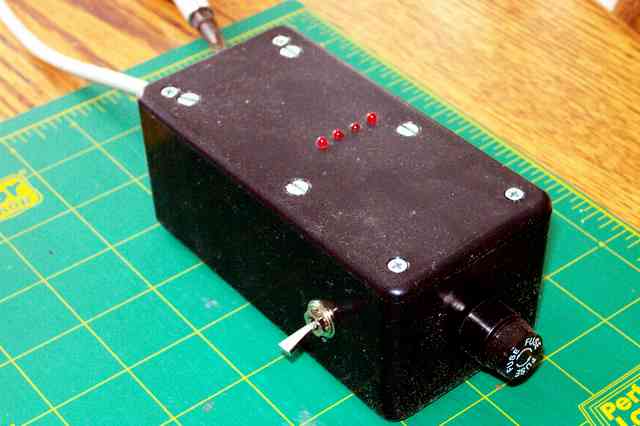
Main Controller Unit
This view shows the Power on-off switch and the fuse holder.
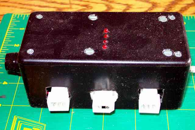
The back side of the main electronics enclosure, showing the fuse holder on the end and the power (center) and two motor connectors on the back side. The row of four LEDs on the top of the box indicates step activity, and are part of the DIY 109 Kit's components.
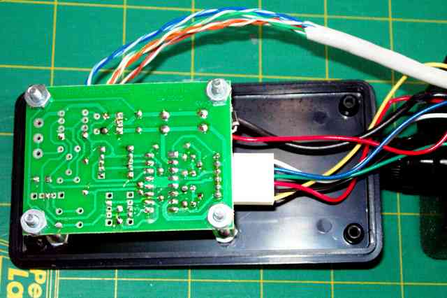
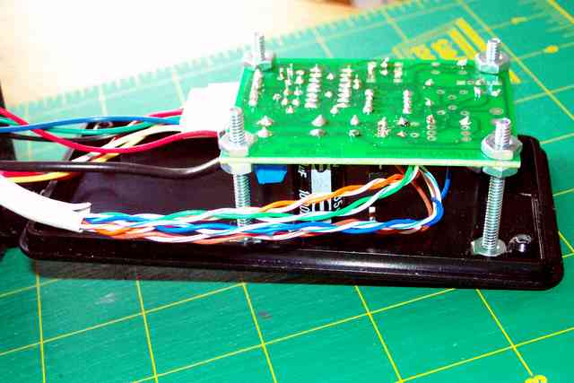
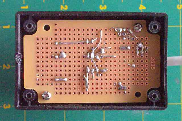
Inside of the main electronics enclosure, the DIY 109 Kit's components
are mounted on the circuit board supplied with the kit. This shows
the bottom of the circuit board -- components are mounted on the other
(top) side.
Note that a
few of the components were not installed on this board, but were
relocated to the circuit board in the hand paddle (see the right
column. The gray cable with the multi-colored twisted paired wires
connects to the hand paddle.
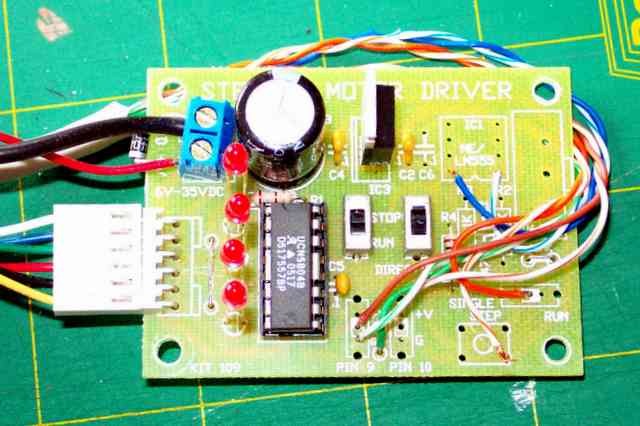
Inside of the main electronics enclosure, the DIY 109 Kit's components
are mounted on the circuit board supplied with the kit. This shows
the top of the circuit board where the kit's components are mounted.
Note that a
few of the components were not installed on this board, but were
relocated to the circuit board in the hand paddle (see the right
column. The gray cable with the multi-colored twisted paired wires
connects to the hand paddle.
This view clearly shows the four LEDs (part of the DIY-109 kit) which serve to show the pulse patterns of the stepper motor drive. They fit into four holes in the top of the controller box.
My Equatorial Platform
Electronic Details
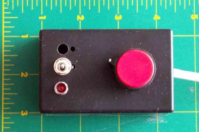
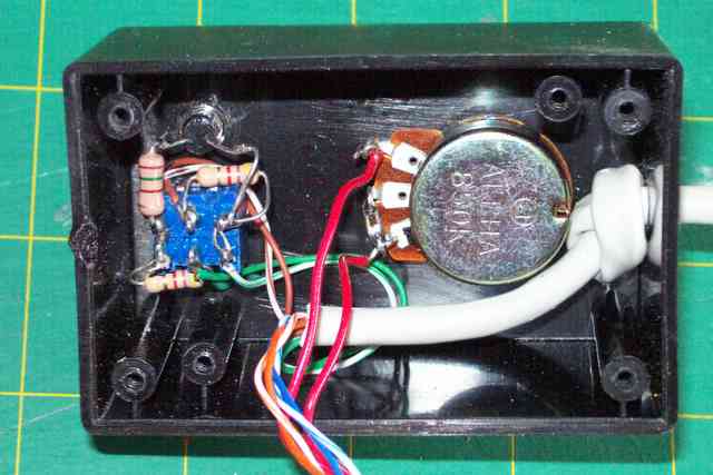
The hand controller contains a variable resistor (potentiometer)
used to adjust motor speed, a three-position (DPDT Center off)
switch used to HOLD, RUN normal, and RUN fast (2x) speed, and
a small LED power indicator which helps find the controller in
the dark!
(Due to internal interference with box ribs, the
planned location for the switch had to be relocated leaving a
temporary ventilation hole. (I had to make up some sort of
excuse for the goof!)
The main circuit's box had a
black plastic cover which was used for its top.
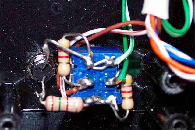
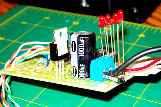
The smaller hand controller project box was chosen because of its size and the fact that it included the small "universal" circuit board. Here you see the bottom (wiring side) of this circuit board, still mounted in its box.
With the circuit board rotated out of the way, you can see the switch, LED and variable resistor (potentiometer) that are mounted on the box case.
The top or component mounting side of the hand controller
circuit board shows:
Because I had 4-pair (8 conductor) wire
(actually bulk ethernet patch cable) I chose to use separate
pairs for the +5 volt power/power ground and for the pulse
output and its ground.
Theory says this should minimize
interference to or from other electronic apparatus, but
if there had been only 5 or 6 conductors, a common ground
wire would have been quite sufficient. In any case, the
power and pulse ground cable connections are tied to a
single point on the hand controller circuit board.
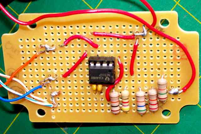
The wiring for the Hold/Normal/2X switch is
shown in this picture. This is a normal
Center Off Double Pole Double Throw switch,
which has three positions.
Again, because I had plenty of conductors in
my cable to the main unit, I used separate
pairs as follows:
The switch was configured to set the Pin 9 and
Pin 10 signals to give Single Phase (full step)
levels when in "2X" position, and Pause levels
when in "Hold" position.
When the switch is in its center (normally used
as an "Off" position) the two resistors shown
connect one lead to +5 volts and the other to
ground, to achieve the levels needed for the
"Normal" speed (which operates the stepper motors
in half step mode).
Since there is +5 volt and ground levels in the
vicinity, this was also used as the source for
the power indicator LED (which can be seen at
the left of this picture).