Click on the diagram or pictures to see a larger view -- use your browser BACK button to return to this page.
Schematic Diagram
The back side of the main electronics enclosure, showing the fuse holder on the end and the power (center) and two motor connectors on the back side. The row of four LEDs on the top of the box indicates step activity, and are part of the DIY 109 Kit's components.
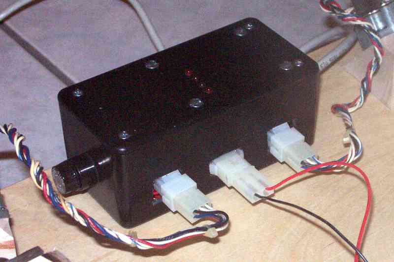
The hand controller contains a variable resistor (potentiometer) used to adjust motor speed, a three-position (DPDT Center off) switch used to HOLD, RUN normal, and RUN fast (2x) speed, and a small LED power indicator which helps find the controller in the dark!
My Platform Electronic Components
Requirements
The principal requirement for the electronic circuit is to provide a steady stream of pulses to the stepper motor windings to cause it to rotate at a speed which will in turn rotate the platform at siderial speed.
For our purposes, it is sufficient to consider the siderial speed to be one revolution every 1436 minutes (a solar day is 1440 minutes [24 x 60], but this is slightly slower than the rotation of the earth relative to the stars).
As my platform was designed, the radius of the north sector is about 19.3 inches (490 mm). I was able to obtain neoprene "drive wheels" from McMaster-Carr with a 3/32 inch (about 2.4 mm) shaft bore to fit my Hurst stepper motors, and a 1/2 inch (about 12.7 mm) outside diameter. This gives a reduction ratio of 19.3/0.25 or 77.2:1.
Given the platform rotation rate of 1/1436 rev/min, the motor output shaft will rotate once every 18.6 minutes. The Hurst stepper motor includes a 300:1 reduction gear, giving 28800 half-steps per revolution. Doing the arithmetic, this gives 1548 steps per minute or 25.8 steps per second.
Other requirements are to have a convenient control for fine tuning the motor speed. I chose to use the DIY Kit 109 half-step mode for normal operation, and arranged controls such that it could also be paused or run in full-step mode to assist in centering the telescope's field.
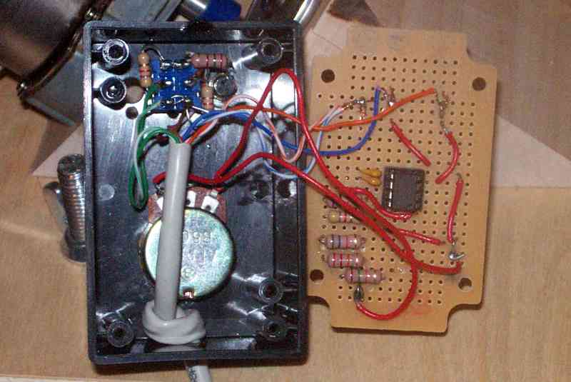
The DIY 109 Kit Assembly
In the schematic diagram in the upper left, you will see two red dashed-line loops, and several red Xs. I added these to indicate the components I mounted in the small hand-control box, as well as the points (Xs) where I inserted about 7 feet (2 meters) of Cat-5 LAN Patch Cable (which I just happened to have on hand). The Patch Cable is more flexible than standard LAN cable, which I thought would be an added feature.
Things I needed to add to the circuit (or replace) included replacement of the 1 Megohm variable resistor ("POT" in the diagram) used for the speed control, and the two 1 Kilohm resistors, "R2" and "R3". These three components, along with the capacitor marked "C1 - 474", control the timing of the NE555 Timer integrated circuit.
You will find that the tolerance of the "C1 - 474" capacitor may allow it to range from about 0.35 microfarads up to 0.60 microfarads (the nominal value is 0.47 microfarads). As a result, your mileage may vary just from this one factor, even if you wanted exactly the same motor speed I did.