Click on the diagram or pictures to see a larger view -- use your browser BACK button to return to this page.
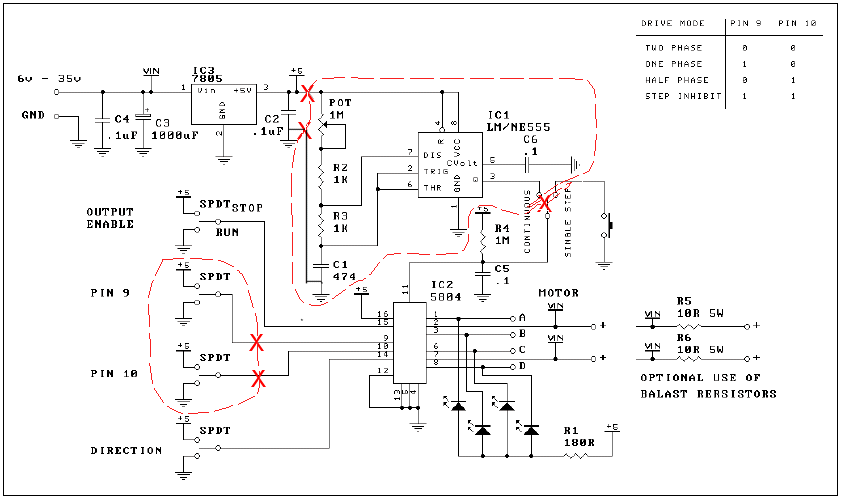
Schematic Diagram
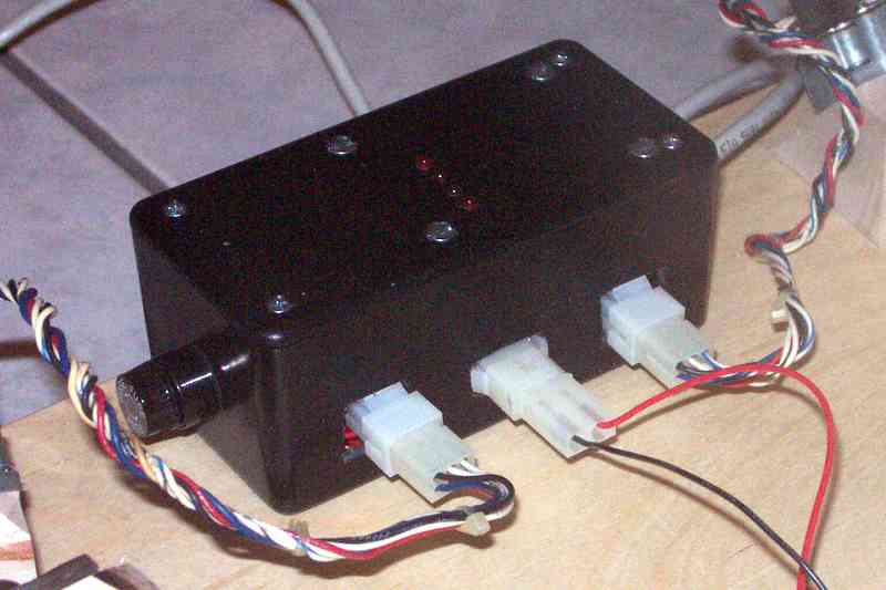
The back side of the main electronics enclosure, showing the fuse holder on the end and the power (center) and two motor connectors on the back side. The row of four LEDs on the top of the box indicates step activity, and are part of the DIY 109 Kit's components.
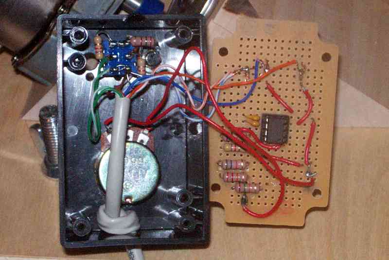
The hand controller contains a variable resistor (potentiometer) used to adjust motor speed, a three-position (DPDT Center off) switch used to HOLD, RUN normal, and RUN fast (2x) speed, and a small LED power indicator which helps find the controller in the dark!
My Platform Electronic Components
Design considerations
The electronic design considerations included minimizing and simplifying the interconnection between the main electronic controller box containing the original DIY 109 Kit circuit board, and the hand controller box.By moving the entire NE555 timer integrated circuit and its related components into the hand controller, it was only necessary to send power to the hand controller and get the step pulses back from it. Both of these were low impedance sources, so noise pickup should be minimal. As I also chose to remote the switching functions which allowed control of HOLD, RUN normal, and RUN 2x speed, this only required two more signal wires, the DPDT switch and two resistors.
Timing component adjustment
NE555 data sheets indicate that the frequency of the timer output is given by the expression
F = 1.44 / (((R2+ POT) + 2 x R3) x C)
First, I built the timer components as included in the kit, and determined that speed was much too fast, and the supplied 1 Megohm adjustable resistor (POT) did not provide a precise adjustment.
Using ohmmeter measured values for my resistor values, I calculated the actual value for C, which in my case was 0.40 microfarad.
The calculated value of total resistance needed to have 25 pulses per second was 140 Kilohms. As I changed the value of R3 from 1 Kilohm to 10 Kilohms, the (2 x R3) term was 20 Kilohms, and the total resistance of the (R2 + POT) combination was 120 Kilohms. In addition to the mid-range 24 Kilohms of the POT, I needed 96 Kilohms of fixed resistance. The calculations involved are simple arithmetic, but I created a simple spreadsheet (I don't have a sliderule anymore!)
Requirements summary
- Timing circuit to provide 25 pulses per second to stepper driver.
- Stepper driver capable of half-step driving of Hurst stepper motor.
- Smaller (50 Kilohm) variable resister (POT) to replace the supplied 1 Megohm POT.
- Change R2 to 96 Kilohms
- Change R3 to 10 Kilohms
- Separation of timing components into hand controller