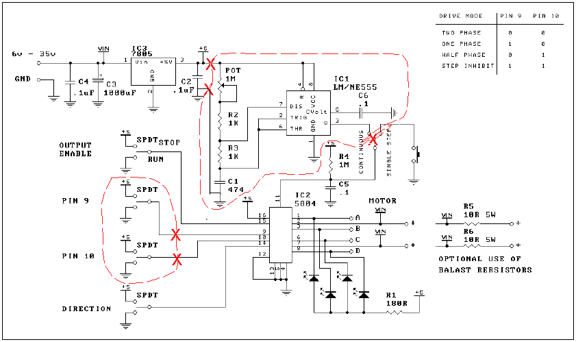
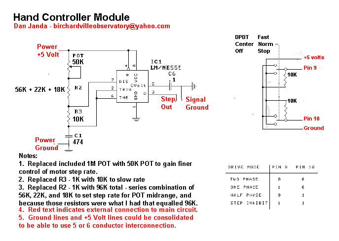
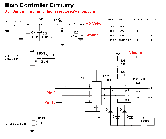
Click on the diagram or pictures to see a larger view -- use your browser BACK button to return to this page.
DIY 109 Schematic Diagram
The DIY 109 Kit was separated into two sections --
a hand controller including the timing circuitry,
and the remaining (Main Controller) components.
The hand controller contains a variable resistor (potentiometer)
used to adjust motor speed, a three-position (DPDT Center off)
switch used to HOLD, RUN normal, and RUN fast (2x) speed, and
a small LED power indicator which helps find the controller in
the dark!
The main controller enclosure contains the original DIY 109 kit's components that were not included in the hand controller. The two motor connectors are wired exactly in parallel. The DIY 109 Kit provides four LEDs which indicate the motor winding state, and help clumsy amateur astronomers find their equipment in the dark.
My Platform Electronic Components, Continued
Hand Controller Ideas
The Hand Controller encloosure needs to house the circuit components that must be manipulated -- the Step Rate control and the Pause/Normal/2x Switch.
The switch changes DC levels at low current, and can be readily separated from the main circuit components.
The Step Rate control potentiometer controls the rate of charging of the timing capacitor, and current through this potentiometer varies as the timing circuit generates its step pulses. Because of this, it was judged wise to have the timing sensitive components (those directly associated with the type 555 Timer integrated circuit) located in the hand controller as well.
I used 4-pair (8 conductor) CAT-V patch cable to connect the hand controller and the main circuitry. This has the advantage of being made of stranded conductors which are then in turn twisted into pairs to minimize interference pickup or radiation. Although strain relief components are available, I chose to use a close fit hole and an overhand knot to restrain the cable. If a conductor ever breaks, I have a large spool of cable I can use for replacement purposes, if the cable length becomes too short because of previous break repairs.
Since the cable had enough conductors, I chose to use a balanced pair for the power (+5v and ground) connections, and another balanced pair for the circuit output (Step Out and ground). I used the other two pairs for the switch connections.
Switch Circuit Design considerations
Pin 9 and 10 of the 5804 Stepper Motor Controller integrated circuit provide four output modes:- Two Phase output (higher torque and current load)
- One Phase output (lower torque and current load)
- Half Phase output (motor runs at half the speed of the two previous output modes)
- Hold or Pause output (motor coils hold current position)
I needed three states -- Pause, Normal (stepping at Half Phase), and 2x (stepping at full speed, twice normal). I did not need availability of both two and one phase output, as they both provide the same speed.
As you can see in the Hand Controller Schematic, the switch is wired to set full speed in the "up" position, and hold or stop in the "down" position. The center-off DPDT switch provides a center position with no contacts connected. I simply used 10K resistors to pull the Pin 9 and Pin 10 connections to the levels needed to set Half Phase operation. See the truth table on the schematic for the hand controller.


