Click on the diagram or pictures to see a larger view -- use your browser BACK button to return to this page.
Schematic Diagram
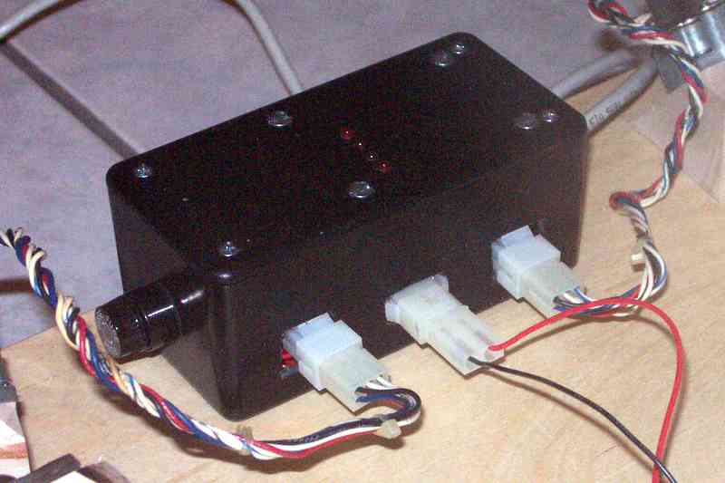
The back side of the main electronics enclosure, showing the fuse holder on the end and the power (center) and two motor connectors on the back side. The row of four LEDs on the top of the box indicates step activity, and are part of the DIY 109 Kit's components.
The hand controller contains a variable resistor (potentiometer) used to adjust motor speed, a three-position (DPDT Center off) switch used to HOLD, RUN normal, and RUN fast (2x) speed, and a small LED power indicator which helps find the controller in the dark!
My Platform Electronic Components, continued
Requirements
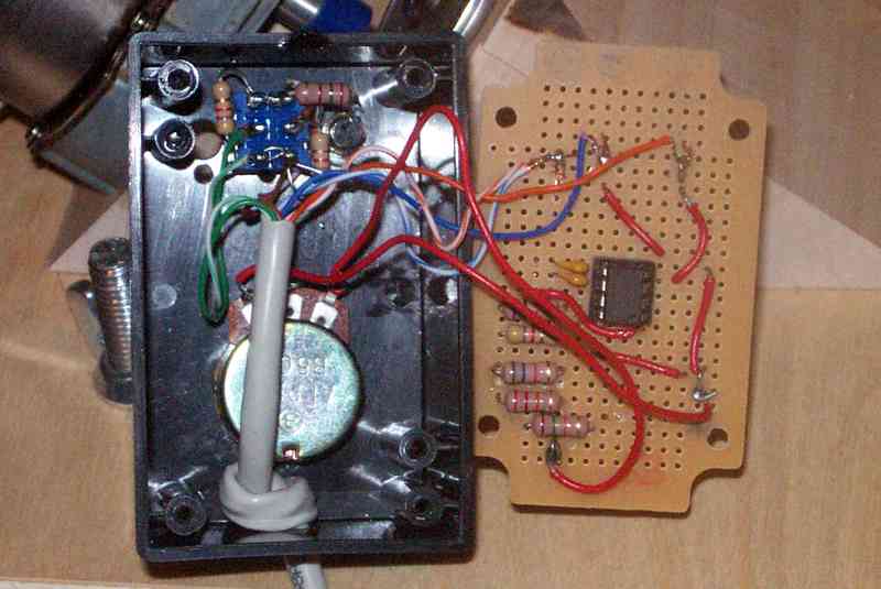
One additional requirement was that the driver circuit should be able to drive two stepper motors connected in parallel (effectively 50 ohms of motor resistance). The DIY Kit 109 uses the UCN5804B integrated circuit to control the current to the stepper motor windings, with a limit of 1.25 amperes of current. With 12 volts across 50 ohms motor windings, Ohm's Law indicates the current will be about 0.25 amperes, well within the safe limits of the UCN5804B.
Electronics Assembly
I obtained a Radio Shack project box 5 x 2-1/2 x 2 inches (about 130 x 65 x 50 mm) to hold the DIY Kit 109 circuit board, together with a power switch and fuse holder, and connectors for power to the system and to connect the motor cables. My motors came with 6-pin Molex connectors, so I bought chassis mountable connectors that mated with them. Although it's bad form, I simply drilled a 1/4 inch (6 mm) hole in the end of the box opposite to the fuse holder to pass the cable.
The hand controller was built in a Radio Shack project box measuring 2 x 3-1/4 x 1-1/2 inches (50 x 80 x 40 mm) which included a small printed circuit prototype board that would be suitable for mounting the components associated with the NE555 timer integrated circuit.